Thursday, April 11, 2013

Automatic Transmission

The concept of an automatic transmission is new in India. An automatic transmission is a motor vehicle transmission that can automatically change gear ratios as the vehicle moves, freeing the driver from having to shift gears.  In this transmission system the gears are never physically moved and are always engaged to the same gears. Automatic transmissions contain mechanical systems, hydraulic systems, electrical systems and computer controls, all working together in perfect harmony manually.
Main Components of an Automatic Transmission-
1.      Planetary Gear Sets
2.      Clutches and Bands
3.      Torque Converter
4.      Valve Body


Wednesday, April 10, 2013

Comparison between MacPherson Double Wishbone Suspension System


Two of the most popular suspensions systems for passenger cars today are the double wishbone suspension system and the MacPherson’s strut suspension system. While it is more usual to see the double wishbone system at the rear end of the car,  MacPherson’s solution normally finds its place at the front end of the car. Both types of suspensions have their own sets of benefits and limitations, thus let us look at both the advantages and disadvantages of both systems, starting with the simpler of the two, the MacPherson struts.

MacPherson Struts- The struts are designed with more simplicity, and thus takes up less space horizontally. As a result, passengers get more compartment place in the car. They also display low un-sprung weight, an advantage that reduces the overall weight of the vehicle as well as increases the car’s acceleration. Lower un-sprung weight also makes your ride more comfortable. Another major advantage of this system is its ease of manufacturing as well as low cost of manufacture compared to other stand-alone suspension systems. Without an upper arm, the suspension system designers can directly block vibration from reaching the passenger compartment.
Nevertheless, the MacPherson struts come with their own drawbacks. Being a long, vertical assembly, you would encounter difficulties if you lower your car as they may be collision with the structure of your car. Thus they do not work well with racing cars that are normally lowered. The MacPherson struts also have problems working with wider wheels that have increased scrub radius, where you would need extra effort to navigate your car in this situation. There is also the problem with the small camber change with vertical movement of the suspension, which could mean the tires have less contact with the road during cornering. This could reduce handling abilities of your vehicle.

Double Wishbone Suspension System- One of its primary benefits is the increase of negative chamber as a result of the vertical suspension movement of the upper and lower arms. This translates to better stability properties for the car as the tires on the outside maintain more contact with the road surface. Handling performance also increases. The double suspension system is much more rigid and stable than other suspension systems, thus you would realize that your steering and wheel alignments are constant even when undergoing high amounts of stress.
Moving on to the drawbacks of the double wishbone suspension system, it is normally bugged by cost issues as it is a more complicated design to produce. There are many parts to the system, and thus every time any of these malfunction of fail, your whole system fails. Repair, modification and maintenance costs and complexities for double wishbone suspension systems are normally higher due to these reasons. This suspension system also proves to be flexible for design engineers, as the arms of the system can be fixed at different angles to the surface, parameters such as camber gain, roll center height and swing arm length can be determined and designed flexibly to suit and road surface in condition.

As we have seen, both suspension systems have their own plus points and limitations. To conclude, double wishbones may perform better, but the MacPherson struts would prove to be more affordable in the long run.

Sunday, April 7, 2013

Volvo MD5A Marine diesel engine WORKSHOP MANUAL

Volvo MD5A Marine diesel engine WORKSHOP MANUAL. This workshop manual contains repair instructions for the MD5A marine diesel engine. The instructions concerning overhauling describe the most suitable working method to be used with the special tools listed under the heading “Special tools”. Both the engine designation and its serial number must be clearly stated in all correspondence concerning the engine and when ordering spare parts. We reserve the right to carry out design modifications and, for this reason, the contents of this manual cannot he regarded as binding. Technicians have long since tried to establish an internationally standardized system of measurements. In 1960 a decision was made to use a system called SI (Systéme International d’Unites). To a large extent, this system is based on earlier systems but the units have been made uniform so that no conversions are necessary.

The SI-system is now being applied within industry in Europe, This manual contains the new SIunits. The units used previously however, are also stated but in brackets. Drain the cooling water and the oil from the engine. Clean externally afterwards. Loosen the water hose between the gearbox and the sea -water pump and remove the gearbox. 3. Remove the rocker cover and the fuel pipe between the pump and the injector and unscrew the rocker gear. Note! Pull the rocker gear straight up since it is centred with a guide pin 1. The other hole 2 is an oil channel.

Download: Volvo MD5A Marine diesel engine WORKSHOP MANUAL

Saturday, April 6, 2013

The Way to Replace an Engine Mount


As a general rule, if you dont absolutely need to replace the engine mount, never change it. Ooly if you have change an engine that needs different mounting mechanisms or the old one have breakdown and the engine cant fits closely into its mount or block anymore. Its better just tightening them rather than changing it entrely.

However, if you actually need to replace the engine mount, Ill give you a simple guide to resolve it. As we know, each engine mount can be different from another, so this is just a general guideline. Since most mounts share the same characteristics so this guide would be a good start.
1) Lifting the engine - Make sure you have a hoist on hand because in order to get to the mounts and replace them, you would need to remove the engine motor. Of course, you would not need to dismantle other parts of the vehicle like the transaxle or transmission but the engine needs to come out nonetheless. In the process of taking out the engine, you just need to remove the bolts that connect the mount to the chassis. Once that is done, the engine block can easily be lifted to give you access to the mount.
2) Removing the old mount - The mount is held to the block by 4 bolts and these need to be removed. If you are thinking of changing the bracket that connects the mount to the chassis then it needs to come out as well.
3) Putting in the new mount - Once the old mount is out, just put the new one in its place and tighten it as far as it can go (without breaking of course.) This will ensure that you do not suffer "noise" from a loose engine mount in the future. When the new mount is in place, gently lower the engine back to the mount until it sits snugly in its position. When they are all lined up, tighten the bolts while the engine is still on the hoist as it will make the process easier.
4) Reconnecting the engine - Reconnect all the engine parts that you have taken out in step 1 such as wire harnesses, lines and hoses. Ensure that you got everything in its right place.
5) Final check - Push down hard on the engine to ensure that it sits tightly in the mount. The engine must not move from its place when force is applied on it.
6) Test - Start the engine and if possible take it for a test drive to see if everything is fine. Should the engine not start, then go back and check on the connections that you have removed in the first place.

Friday, April 5, 2013

1991 Mitsubishi GTO 3000GT Repair Service Manual

1991 Mitsubishi GTO 3000GT Repair Service Manual. The Mitsubishi GTO is a sports car built by Japanese automaker Mitsubishi Motors between 1990 and 2001, although in most export markets it was rebadged as a Mitsubishi 3000GT ( wikipedia ). This following is Factory Service Manual for Mitsubishi GTO / 3000GT 1991 ( 1991 ) , this service manual cover Engine / Chassis / Body only.

Download: 1991 Mitsubishi GTO 3000GT Repair Service Manual

Thursday, April 4, 2013

2005 Hyundai Santa Fe Owners Manual

2005 Hyundai Santa Fe Owners Manual. User and Operator’s Manual for 2005 Hyundai Santa Fe. Engine Type: 2.7 V6 (2,656 cc) and 3.5 V6 (3,497 cc) 6-Cylinder V-type DOHC. Free PDF Service and Owner’s Manual Download.Table of contents Features of your Hyundai Driving Hazard Warning System.1-62 Heating and Cooling Control. 1-92 Heating and Ventilation Air flow control.1-94 Air intake control switch.1-93 Bi-level heating. 1-98 Defrosting / Defogging. 1-101 Fan speed control (Blower control). 1-93 Temperature control. 1-97 High-Mounted Rear Stop Light. 1-83 Homelink Mirror.1-76 Hood Release.1-85 Horn. Warning and Indicator Lights.1-48 Windows Power. 1-11 Windshield Wiper and Washer. 1-60 Rear window wiper and washer. 1-61 Windshield Wiper Blades.6.


Download: 2005 Hyundai Santa Fe Owners Manual

Wednesday, April 3, 2013

Audi A3 City Lights for the US A3 with Bi Xenon Headlamps

The lighting configuration of cars in Europe (and most of the rest of the world) generally includes city lights - small (5w) bulbs located in the left & right headlamp reflectors which make them glow, but not really project any light. They serve the purpose of front parking lights.

Until US automotive lighting regulations began to be reformed in the late 1980s and 1990s, headlights had to be physically separated from other lights, like parking lights and turn signals. Therefore, city lights were not permitted in US-spec headlamps. Under current regulations, though, lights may be combined into common lens/reflector assemblies, as long they meet their individual requirements. That means that city lights are permitted, and they may even serve as front parking lights if they otherwise meet the right criteria. Some VWs (like the Mk4 Golf/GTI) are good examples of this.

The halogen and xenon/halogen headlamps that Audi installs in the US A3s do not have city light bulbs at all. The A3 sidemarkers are curved to be visible from the front as well, so Audi got the car approved with only the US-required amber sidemarker/relfector lights as front parking lights. On the cars with bi-xenon headlamps, city lights are present in the inner (DRL) reflector. They are wired internally within the headlamp assembly, but the wiring harness that plugs into the headlamp assembly does not have a wire going to the pin that powers the city light bulbs.

Some simple circuit tracing determined that Pin 10 on the headlamp plug goes to the city lights. All that is needed is to run a new circuit from the +12v of the left & right sidemarkers to Pin 10 of the respective headlamp plugs.

Teminology note: The lights on the front bumper are sidemarkers. They come on with the parking lights and headlights, are required to illuminate amber, and also serve as the required amber passive reflectors. The lights farther back on the fender are not sidemarkers, they are repeater turn signals. They are required in many countries; in the US they are permissable, but not required.

Materials:
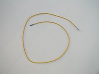
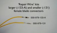
You will need a minimum of 1 repair wire from Audi, which can be obtained from your parts department. They are a length of wire with a connector (the same one) on each end. There are various connectors, for this project you will need part number 000-979-133-A, a female blade connector. You cut the wire in half to give you one connector/lead for each headlamp plug that youll be upgrading (left & right), then you can trim the wire down later.


Repair wire:


Comparison of two sizes of the repair wires, with part numbers. The larger one (-133-A) is whats used for this project.


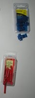
You will need some common tools, and a wire strip/crimp tool (dont try to substitute pliers). In addition to a roll of electrical tape, you should also have a can of StarBrite Liquid Electrical Tape (I got it at Home Depot). For the actual connections you will need a roll of 18 gauge wire (black is good for these runs), some 18-22 gauge crimp-on butt splices, and some 18-22 gauge tap splices:


Procedure:
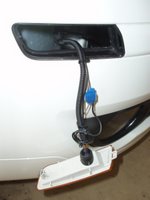
First you have to remove the sidemarker lights from the bumper. The left side is easy - just open the hood, reach down below the headlamp to the back side of the sidemarker, and release the clip to pop it out from the bumper. The right side is not so easy. You have to carefully pop out the black plastic grill around the right foglamp, and reach up to the back side of the right sidemarker from below. To remove the foglamp grill (not shown here), there are two clips (top and bottom) on the end fartherest from the foglamp that you can release with a flat screwdriver.

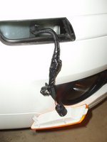
Well start with the right side. When you have the light popped out of the bumper, you will find two wires going to it. The brown one is the ground - leave it alone. The other one is the + lead. Pull it out of the split plastic conduit, and use one of the tap splices to connect your new wire to it. Always leave a little extra coil of your new wire tied up in case you have to redo something later:


Then, coat and seal the splice with the liquid electrical tape, and wrap it tightly with regular electrical tape. If done right, it will form a completely waterproof connection. Zip-tie this tightly to the original conduit:


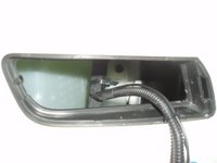
Run the wire in along the existing harness, zip-tying it as you go. Reaching in through the light opening for that fartherest one requres skinny hands and long-nose pliers:


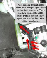
On the right side, there is a rigid plastic cable chase that part of the wiring harness runs through, underneath the neck of the washer-fluid tank. There are two snap clips holding it closed. I managed to get them open and run the wire through the cable chase, then snap it closed again. This keeps it out of the way, completely hidden and protected, and looks original. Getting the snaps open and the wire in there required a heavy wire with a hook bent in the end (made from a clotheshanger):


Now we have the wire up to the headlamp plug, and are ready to attach it. Lets do the left-hand side first, though:
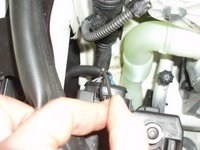


The left light is a lot easier to do. Pop the light out as described above. If you pull the socket out of the lens, you can just pull the harness up where you can reach it from the top by the headlamp. As with the right one, leave the brown (ground) wire alone, attach your new wire with the tap splice, and seal with with the liquid/regular tape as described (photo shows the splice before being sealed & zip-tied).
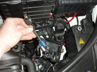


The left side only takes a short run of wire, zip-tied to the existing wiring harness, to reach the headlamp plug. Now were going to install the new female connector into the headlamp plug.
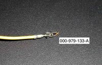


Remove the plug from the headlamp assembly. Theres a little cap around the back side of the plug, release two clips and take it off (not shown here). Locate position 10 - it should have a rubber plug in it with no wire present. Use a small nail in a pair of locking pliers to pluck the rubber plug out:
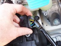


Using the same nail, pierce the rubber plug lengthwise. Its already partially started, so youll be able to see what to do:


Pass the new repair wire through the hole in the rubber plug, making sure its in the orientation shown here:
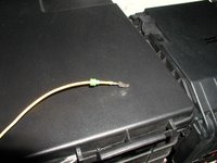


Now you have to get the new female connector into the headlamp plug. You first have to unlock the plug. If you look closely at the purple part of the plug, youll see an arrow molded into it showing the lock direction. Stick a flat screwdriver between the purple part and the surrounding black part on the CURVED side of the plug, and slide the purple part (it moves less than 0.5mm) until it clicks.

Then you can insert the new female connector into position 10 from the back side of the plug, until it clicks in firmly. It only fits in one way - you can figure it out. If you cant get it all the way in until it clicks, make sure you unlocked the purple part as described above. When finished, tt should look from the front just like the others in the plug, and you should seat the rubber plug into the hole behind it so that it looks like the other wires (make sure you slide the purple part the other way to lock it again):
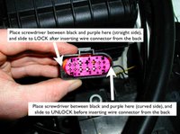


Use a butt-splice to join the wire you ran from the light to the end of the repair wire you just installed in the plug. Youll need to do some trimming, and the splice should look like this:
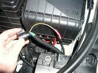


Again, seal the splice. Dont use too much tape, so you can squeeze it into the split plastic conduit, then zip-tie it securely together. Snap the cap back around the back of the plug (shown here completely together and ready to plug in):


Replace the plug in the headlamp. (If it wont fit in, did you lock the purple part as described above after installing the connector?) Reassemble and replace the sidemarker light into the bumper.

Repeat the process for wiring the plug on the right headlamp.

Test, and you should have....
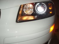
...working city lights!

If you do this mod, please email me and let me know how it goes. Photos of your wiring steps are appreciated - Im curious how other people replicate this process.